

Анализ метода установки фильтра DINF1-Y
Время выпуска:
Jul 30,2025
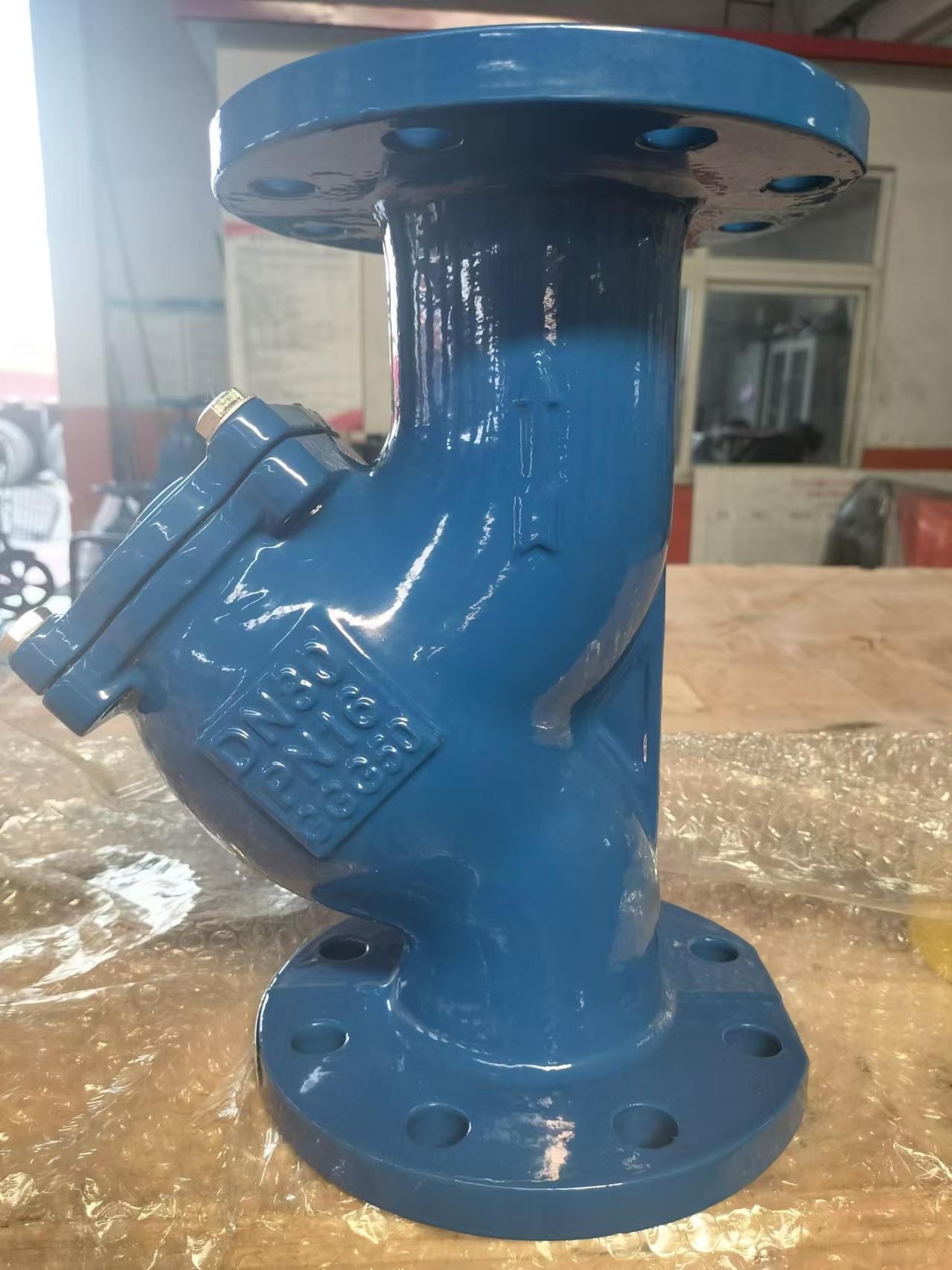
The Y-shaped filter has a simple and reliable structure, and is an essential component for protecting pipeline system equipment from particle damage. Understanding its Y-shaped structure, impurity interception principle, as well as flow direction and installation direction (especially the fact that the discharge outlet must be downward or convenient for discharge) is the key to correct selection, installation, and maintenance. Regular discharge and cleaning are necessary guarantees for maintaining its efficient filtration performance
Proper installation is crucial for the performance and lifespan of Y-shaped filters. Please be sure to follow the following points:
Flow direction: the most crucial point! The fluid must flow from the "dirty side" (outer side) of the filter to the "clean side" (inner side).
Standard installation: The fluid inlet faces the outside of the filter (i.e. the opening direction of the "Y" branch), and the fluid outlet faces the inside of the filter. Usually, there are flow arrows indicating the direction on the valve body.
Strictly prohibit reverse installation! If installed in reverse, impurities will be directly flushed to downstream equipment, losing their filtering function, and the filter screen may be deformed or damaged due to flushing.
Direction:
Horizontal pipeline: This is the most common installation method. The filter must face downwards (with the discharge outlet facing vertically downwards). This way, impurities naturally settle into the drainage chamber at the bottom of the filter screen by gravity. If the discharge outlet is facing upwards or sideways during horizontal installation, impurities cannot be effectively settled and discharged. The main pipeline can be horizontal or slightly inclined.
Vertical pipeline: Fluid must flow from top to bottom. At this point, the filter screen and sewage outlet should be in a horizontal direction (facing the side). Ensure that the sewage outlet is easy to operate. It is strictly prohibited to install from bottom to top! This installation method can accumulate impurities at the top of the filter, making it difficult to discharge and even potentially crushing the filter.
Installation location:
Upstream of protected equipment: installed before equipment that needs protection such as pumps, valves, flow meters, heat exchangers, etc. For example, before the pump inlet, control valve, flow meter, drain valve, pressure reducing valve, etc.
Easy to operate and maintain: Installed in an easily accessible location, it facilitates drainage operations, disassembly of end caps, cleaning/replacement of filters.
Provide support: For large or heavy filters, or installed in areas with high vibration, the pipeline needs to provide sufficient support to avoid additional stress or connection leakage caused by the filter's own weight or vibration on the pipeline. Do not rely solely on pipeline connections to support the weight of the entire filter.
Discharge outlet configuration:
It is strongly recommended to install a shut-off valve or ball valve (drain valve) at the discharge outlet. This is much more convenient than using only a plug, as it allows for drainage (pressurized drainage) during system operation without the need for shutdown.
Leave enough space below the drain valve to connect the drain pipe (leading to a trench or collection bucket) or place a container to catch the discharged dirt, avoiding environmental pollution and burns (high-temperature fluid).
Space considerations:
During installation, reserve sufficient space in front of the filter end cover (cover plate) so that the end cover can be easily removed and the filter can be taken out during maintenance.
Connection method:
According to the design of the pipeline system, choose the appropriate connection method: flange connection (most common), threaded connection (NPT, BSP), welding end connection (Welding End), socket weld connection (Socket Weld). Ensure a secure connection and good sealing.
Горячий Новости

-Контакты Нас
WhatsApp/WeChat:
Электронная почта:
Добавить:
Город Ботоу, провинция Хэбэй, деревня Шуанши Чжао

Здравствуйте. что я могу для Вас сделать?
Мы свяжемся с вами в течение одного рабочего дня. Обратите внимание на свою электронную почту.